BASIC OF PYTHON PROGRMMING

BASIC OF PYTHON PROGRMMING


i am professional electrical engineer, i have two years experince of electrical maintenanace in STP plant.
here we provide articles on electrical engineering ,PPT Presentation, python programming,SEO,Fitness etc.

here we give awesome feature like logo design,email scraping,PPT desing,electrical engineering articals.
we provide the animated ppt presentation with nice effect like parallex,video ppt etc .
we provide responsive and nice desings.
we provide modern desing of logo and PPT.
BASIC OF PYTHON PROGRMMING

Transformers
• A transformer is a static device
that transforms electric energy from one ac voltage level to another. It is
this device that has made the electric system almost universally AC. The
electric power is generated at relatively low voltages (up to a maximum of 33
kV) which then is raised to very high voltages (e.g. 756 kV) by means of a
transformer and then transmitted.
• High voltages are associated with low
currents and reduced transmission losses.

• The core
which supports the transformers mechanically and conducts their mutual flux, is
normally made of highly permeable iron or steel alloy (cold-rolled, grain
oriented sheet steel). Such a transformer is generally called an iron-core
transformer.
• However in special cases, the magnetic
circuit linking the windings may be made of non-magnetic material, in which
case transformer is referred to as an air-core transformer.
• Air core
transformer used in radio devices and in certain types of measuring and testing
instruments.
• The
magnetic core of the transformer is made up of stacks of thin lamination of
0.35 mm thickness of CRGO lightly insulated with varnish, this material allow
the use of high flux density [ 1-1.5 T] and its low loss property together with
laminated core reduces the core loss to fairly low values.
Core Type
transformer: -
• In core
type transformer windings are around two legs or three legs (depend on their
phases) of the rectangular magnetic core.
•
Rectangular magnetic core is made by using the E and L shape of the sheets.
• Though
most of the is confined to a high permeability core, some flux always leaks
through the core and lies in air called leakage flux.
• Leakage is reduced by bringing the two coils
closer. In core type we achieve this by using L.V. and H.V. on each limb of the
core.

Shell type
transformers: -
• In this
type of the transformer windings are wound on the central leg of a three legged
core.
• Leakage in
shell type transformer is reduced by sub-dividing each winding into sub-section
and interleaved in L.V. and H.V winding.

Conservator:
-
Power
transformer is provided with a conservative through which transformer breaths
into air. It is a small size tank placed on the top of main tank. It prevents
fast oxidization and consequent deterioration of insulating properties of oil.
Explosion
vent tube: -
Purpose of this is to prevent damage of
transformer tank be releasing any excessive pressure generated inside the
transformer.
Radiator: -
Breather: -
• When the
temperature change occurs in transformer oil, the oil expands or contracts.
There is an exchange of air also occur when transformer is fully loaded.
• When the
transformer gets cooled then oil level gets down and when it goes down it
absorbs air this process is called breathing.
• Silica gel
breather controls the level of moisture. Silica gel is used to absorb moisture
content from air.
• When silica gel absorbs moisture, it becomes pink. Generally, its colour is blue.

E.M.F.
equation: -
When a
sinusoidal voltage is applied to the primary winding of a transformer,
alternating flux ϕm sets up in the iron core of the transformer. This
sinusoidal flux links with both primary and secondary winding. The function of
flux is a sine function. The rate of change of flux with respect to time is
derived mathematically.
The derivation of EMF Equation of the transformer is
shown below. Let ϕm be the maximum value of flux in Weber. f be the supply
frequency in Hz. N1 is the number of turns in the primary winding. N2 is the
number of turns in the secondary winding.

As shown in the above figure that the flux changes from + ϕm to – ϕm in half a cycle of 1/2f seconds.
By Faraday’s Law,
Let E1 is the e.m.f induced in the primary
winding
E1 = − dλ /dt
Where λ= N1ɸ
Therefore,
E1 = − N1/ dɸ dt
Since ϕ is
due to AC supply ϕ = ϕm Sinωt
E1 = − N1 d /dt
(ϕm Sinωt)
E1 = − N1 ϕm ω Cosωt
E1 = N1 ϕm ω Sin (ωt− 90°)
So the
induced e.m.f lags flux by 90 degrees.
Maximum
valve of e.m.f,
E1 = N1 ϕm ω
But ω = 2πf
(E1) max = 2πf N1 ϕm
Root mean
square RMS value is
E1= (E1)max √2 …………….(1)
Putting the
value of (E1)max in equation (1) we get

Now,
equating the equation (2) and (3) we get
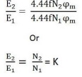
The above
equation is called the turn ratio where K is known as transformation ratio.
Equivalent
circuit of the transformer: -
The
equivalent circuit diagram of any device can be quite helpful in
predetermination of the behaviour of the device under the various condition of
operation.
It is simply the circuit representation of the
equation describing the performance of the device.
The
simplified equivalent circuit of a transformer is drawn by representing all the
parameters of the transformer either on the secondary side or on the primary
side.
The equivalent circuit diagram of the
transformer is shown below

Let the
equivalent circuit of a transformer having the transformation ratio K = E2/E1
The induced e.m.f E1 is equal to the primary
applied voltage V1 less primary voltage drop.
This voltage
causes current I0 no load current in the primary winding of the transformer.
The value of no-load current is very small, and thus, it is neglected. Hence,
I1 = I1’. The no load current is further divided into two components called
magnetizing current (Im) and working current (Iw).
The secondary current I2 is

The terminal voltage V2 across the load is
equal to the induced e.m.f E2 in the secondary winding less voltage drop in the
secondary winding.
Equivalent circuit when all the
quantities are referred to primary side: -
In this case to draw the equivalent circuit of
the transformer all the quantities are to be referred to the primary as shown
in the figure below

The
following are the values of resistance and reactance given below Secondary
resistance referred to primary side is given as

The equivalent resistance referred to primary
side is given as
Req = R1 + R2 ’
Secondary
reactance referred to primary side is given as

The equivalent reactance referred to primary side is given as
Xeq = X1 + X2 ’
Further
simplification of the equivalent circuit of the transformer can be done by
neglecting the parallel branch consisting R0 and X0. The simplified circuit
diagram of the transformer is shown below.
O.C. test and S.C. test: -
The aim of
carrying out O.C. test and S.C. test on a transformer is to predict its
performance without actually loading it.
O.C. Test: -
O.C. test is carried out at rated frequency and rated
voltage to determine the core loss. The iron loss is thus is treated as
constant, in spite of minor voltage variation in voltage and frequency during
actual operation.
This test is carried out with the instruments placed
on low voltage side while the high voltage side is left open circuited.
This is done because it is easier to manage rated voltage
supply at low voltage level rather than at high voltage level. Also the
instruments used are economic in cost and it is easier to work on low voltage
side.
Therefore no load current is limited to 5% of full
load current, a primary winding copper loss is ignored, also the primary
impedance drop at such low current is neglected.
Because no load power factor is very low, it is recommended
that a low power factor wattmeter to be used.

Then the
iron loss of the transformer Pi = W0 and

The no-load
power factor is

S.C. Test: -
S. C. test
is carried out at rated current to determine the full load copper loss.
This test is carried out with the instrument placed
on high voltage side while the low voltage side is short circuited by a thin a
conductor (so that wire will not burn). This is because a rated current is
lower on low voltage side as compared to high voltage side.
Consequently, the instruments are economic in cost
since the voltage required to circulate full load current at circuited would be
about 10% of rated voltage.
The core loss under this low voltage condition is ignored. Also,
the exciting current at such low value of voltage will be completely neglected.
Short circuit test need not to be carried out strictly
at rated frequency because the copper loss that depends upon the winding
resistance is independent of the frequency of the supply as the skin effect in
transformer at power frequency is negligible.
Wattmeter used in this test is of high-power factor.


in substation,
control unit, SCADA unit we use the battery bank for operation of relay and
circuit breaker.
At the condition of supply failure our SCADA
system will not get shut down due the battery bank.
when supply will restore, we required supply
to operate the panel to connect the load, which get form the battery bank
so for
maintain this battery bank continuously charge we required the battery charger.
we used
the float cum boost battery charger to charge the battery bank .
the diagram
for float cum boost battery charger is as shown in fig.

CONSTRUCTION:
-
It contains
the three-phase ac supply with to battery charger is attached.
This three-phase
ac supply is connected to the input of both float and boost battery charger.
Both the
battery charger contains the rectifier circuit at output. Between the both
charger there is VC contactor, which separate both from each other.
It also
contain the battery bank of 110 v .
WORKING: -
From fig, normally
we charge the battery bank form the float charger.
The float
charger input is connected to the 3-phase ac input supply. Then it converted
this ac supply to dc and connected to the battery and also load because it performs
two function:
1.sypply load.
2. charge
the battery.
When battery is completely dead at that condition battery is charged through boost charger which produce large voltage for small time of period to boost the charging.
when we used boost charger at that time float charger is off and also VC contractor is disconnected.
Boost charger
can also supply the load but through diode to limit the voltage. because boost
charger gives 2.6 voltage for each 2v battery, so for 110v it will be 143v and
this voltage is not good to directly connected to the 110v load.
HOW TO
CALCULATE FUSE RATING FOR MOTOR
Fuse rating
for 40 HP 3 phase motor: -


Fuse rating
for 30 kw 3 phase motor: -


jalgaon, maharashtra
patilmilind235@gmail.com
m.kip2611@gmail.com
9975856435


